EMC VPLEX容灾系统实施方案
VPLEX容灾系统实施方案
目录
- 项目介绍 .................................................................................................................. 4
1.1 VPLEX 架构图 ................................................................................................ 4
1.2 本项目设备配置 .............................................................................................. 4
- 存储规划 .................................................................................................................. 5
2.1 规划目标 .......................................................................................................... 5
2.2 VPLEX 端口的使用 ........................................................................................ 5
- SAN 网络规划 ......................................................................................................... 6
3.1 现有拓扑示意图 .............................................................................................. 6
3.2 VPLEX 实施拓扑示意图 ................................................................................ 7
3.3 设备 IP 规划 .................................................................................................... 8
3.4 Zone 规划 ........................................................................................................ 8
- VPLEX Witness 实施规划 .............................................................................. 10
- 版本控制 ................................................................................................................ 11
5.1 ODM 版本的要求 .......................................................................................... 11
5.2 PowerHA 版本的要求 .................................................................................. 11
5.3 Powerpath 版本的要求 ................................................................................ 12
- 与数据迁移相关的 VPLEX 配置 ........................................................................ 13
6.1 应用系统数据迁移方式论述 ........................................................................ 13
6.1.1 主机层面的迁移 .................................................................................. 13
6.1.2 存储层面的迁移 .................................................................................. 13
6.2 应用系统数据迁移实施步骤简述 ................................................................ 13
6.2.1 主机层面在线数据迁移方式实施步骤简述 ................................... 13
6.2.2 VPLEX 层面的离线数据转移方式实施步骤简述 ............................ 14
6.2.3 应用系统从 VPLEX-Metro 回退到 DS4800 存储系统实施步骤简述 15
- VPLEX Metro 实施步骤 .................................................................................. 15
7.1 VPLEX 前期准备 ......................................................................................... 15
7.1.1 system volumes .................................................................................... 15
7.1.2 meta data volumes .............................................................................. 15
7.1.3 logging volumes ................................................................................... 16
7.2 Switch zoning .............................................................................................. 17
7.3 Backend storage provisionq .................................................................... 17
7.4 VPLEX initial setup .................................................................................... 18
7.4.1 Config ip address and hostname of VPLEX ......................................... 18
7.4.1.1 Connect to management server ..................................................... 18
7.4.1.2 entering the VPLEXCLI ..................................................................... 18
7.4.1.3 set the management server ip address .......................................... 18
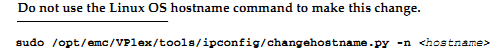
7.4.1.4 change the hostname of VPLEX ...................................................... 18
7.4.1.5 check software version .................................................................... 19
7.4.2 use EZ-setup to initialize the VPLEX1 .................................................. 19
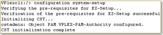
7.4.2.1 Start EZ-setup ................................................................................... 19
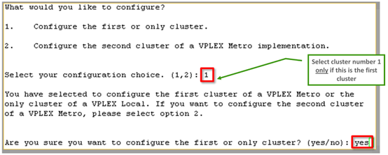
7.4.2.2 Configure the first cluster ................................................................ 19
7.4.2.3 Chose the local authentication ....................................................... 19
7.4.2.4 Configure event notification ........................................................... 19
7.4.2.5 Configure send system report to EMC ........................................... 20
7.4.2.6 Configure performance statistics collector .................................... 20
7.4.2.7 Generate the certificate .................................................................. 20
7.4.2.8 Backend storage discovery .............................................................. 21
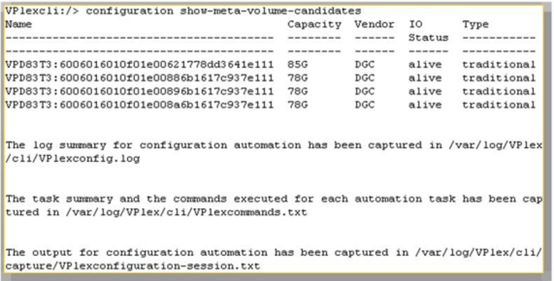
7.4.2.9 create meta-data volume ................................................................ 21
7.4.2.10 verify if meta-data volume is successfully created ................... 22
7.4.2.11 create meta-data volume backups ............................................. 22
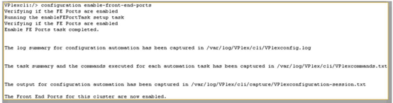
7.4.2.12 enable FE port .............................................................................. 22
7.4.3 use EZ-setup to initialize the VPLEX2 .................................................. 22
7.4.3.1 Connect to VPLEX2 ........................................................................... 22
7.4.3.2 Sychronize the time on the clusters ............................................... 22
7.4.3.3 Start EZ-setup on cluster2 ............................................................... 23
7.4.3.4 Configure the Meta-data volume and backup of VPLEX2 ............. 23
7.4.3.5 Complete configuration of cluster1 ................................................ 23
7.4.3.6 Complete configuration of cluster2 ................................................ 23
7.4.4 Join the clusters .................................................................................... 23
7.4.5 Create logging volumes ....................................................................... 24
7.5 Check the cluster health ......................................................................... 25
7.6 VPLEX backend storage connectivity verify ...................................... 25
7.7 Claim the data volume ............................................................................... 25
- 设备的使用 ............................................................................................................ 28
8.1 Vplex 的使用 ................................................................................................ 28
- 系统测试 ................................................................................................................ 29
9.1 Vplex 高可用测试 ........................................................................................ 29
9.2 数据库高可用测试 ........................................................................................ 30
1. 项目介绍
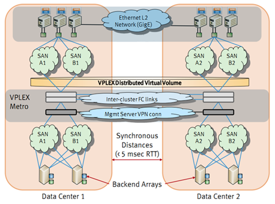
XXX 灾备项目采用 EMC VPLEX METRO 解决方案,实现院区主机房和灾备机房容灾,结合实际情况本项目规划如下。
1.1 VPLEX 架构图
1.1 本项目设备配置
本次规划的 EMC VPLEX 配置简要描述如下:
l 1 个处理器引擎两个控制器, 8 个 8Gb 的 FC 前端口, 8 个 8Gb 的 FC 后端口
l 72GB Cache
l VPLEX METRO 20TB
本次规划的 EMC DS-300B SAN 交换机配置简要描述如下:
l 两台交换机,每台激活 24 个 8Gb 端口。
1. 存储规划
1**
2**
2.1 规划目标
HP 3PAR 和 IBM DS4800 存储使用 VPLEXMETRO 架构,并且满足 VPLEX METRO 双活的解决方案规划如下。
1.1 VPLEX 端口的使用
本项目中 vplex 版本为 vs2 ,每台 vplex 有 1 个引擎每个引擎有两个控制器。每台主机配置了 2 张双口 HBA 卡用于连接 VPLEX ,每张卡使用一个端口, VPLEX 的后端口用于连接 HP 3PAR 和 IBM DS4800 。所有 VPLEX 端口的使用如下表所示:

命名规则
VPLEX 的端口命名规则: E1D0F0 代表引擎 1 的 director A 的 A0 模块的第 0 口
HP 3PAR 的端口命名规则: 3PAR_A_F0 代表控制器 A 的 FC 第 0 口
Zone 的命名规则: VPLEXA_E1B2F2_3PAR_A_F0 代表 VPLEXA 的引擎 1 的 director B 的 B2 模块的 2 口到 3PAR 控制器 A 的第 0 光纤口的 zone
vplex连接交换机端口
vplex连接交换机端口
| Engine No.1 | |||||||||||
| DirctorNo.B | DirctorNo.A | ||||||||||
| FE | SW | BE | SW | WAN | SW | FE | SW | BE | SW | WAN | SW |
| B0F3 | B1F3 | B3F3 | A0F3 | A1F3 | A3F3 | ||||||
| B0F2 | B1F2 | B3F2 | A0F2 | A1F2 | A3F2 | ||||||
| B0F1 | B1F1 | B3F1 | A0F1 | A1F1 | A3F1 | ||||||
| B0F0 | B1F0 | B3F0 | A0F0 | A1F0 | A3F0 |
注:此图为一台 VPLEX 的端口连接图。
1. SAN 网络规划
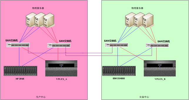
本项目使用主机房的 SAN 交换机及新增的两台 DS-300B SAN 交换机, vplex 到一台交换机需要至少 4 个 FE , 4 个 BE , 4 个 Wan com ,每台存储至少需要 4 个端口。如情况允许,建议在生产机房搭建同机房的 vplex metro 环境,便于下一步的数据迁移。
在数据迁移完成后,灾备机房环境准备好后,把 vplex metro 的 cluster-2 和 DS4800 搬运到灾备机房。此时生产机房和灾备机房 vplex metro 正常运行,不影响原有系统的运行。
1.1 现有拓扑示意图
1.1 VPLEX 实施拓扑示意图
Vplex 在生产中心运行

灾备中心准备好后 vplex 在生产中心和灾备中心运行
## 1.1 设备 IP 规划
| 光纤需求(满配最高带宽设计) | |||
| From | To | 光纤数量(至少数量) | 类型 |
| VPLEX_A | 生产中心SAN交换机 | 12条 | 多模 |
| HP 3PAR | 生产中心SAN交换机 | 4条 | 多模 |
| VPLEX_B | 灾备中心SAN交换机 | 12条 | 多模 |
| IBM DS4800 | 灾备中心SAN交换机 | 4条 | 多模 |
| 网线需求 | |||
| 设备名 | 网线数量 | IP地址 | 备注 |
| VPLEX_A | 1 | 1个 | 生产机房VPLEX管理地址 |
| VPLEX_B | 1 | 1个 | 容灾机房VPLEX管理地址 |
| DS-300B SAN | 2 | 2 | 2个管理IP |
1.1 Zone 规划
生产中心 VPLEX 与第一路 SAN 交换机端口的连接
| Port | VPLEX port | 备注 |
| VPLEX_0001_E1D01F0 | VPLEX_0001的前端端口,连接主机的HBA | |
| VPLEX_0001_E1D02F0 | VPLEX_0001的前端端口,连接主机的HBA | |
| VPLEX_0001_E1D01B0 | VPLEX_0001的后端端口,连接后端存储系统的前端端口 | |
| VPLEX_0001_E1D02B0 | VPLEX_0001的后端端口,连接后端存储系统的前端端口 | |
| VPLEX_0001_E1D01W0 | VPLEX_0001的WAN端口 | |
| VPLEX_0001_E1D02W0 | VPLEX_0001的WAN端口 |
生产中心 VPLEX 与第二路 SAN 交换机端口的连接
| Port | VPLEX port | 备注 |
| VPLEX_0001_E1D01F1 | VPLEX_0001的前端端口,连接主机的HBA | |
| VPLEX_0001_E1D02F1 | VPLEX_0001的前端端口,连接主机的HBA | |
| VPLEX_0001_E1D01B1 | VPLEX_0001的后端端口,连接后端存储系统的前端端口 | |
| VPLEX_0001_E1D02B1 | VPLEX_0001的后端端口,连接后端存储系统的前端端口 | |
| VPLEX_0001_E1D01W1 | VPLEX_0001的WAN端口 | |
| VPLEX_0001_E1D02W1 | VPLEX_0001的WAN端口 |
灾备中心 VPLEX 与第一路 SAN 交换机端口的连接
| Port | VPLEX port | 备注 |
| VPLEX_0002_E1D01F0 | VPLEX_0002的前端端口,连接主机的HBA | |
| VPLEX_0002_E1D02F0 | VPLEX_0002的前端端口,连接主机的HBA | |
| VPLEX_0002_E1D01B0 | VPLEX_0002的后端端口,连接后端存储系统的前端端口 | |
| VPLEX_0002_E1D02B0 | VPLEX_0002的后端端口,连接后端存储系统的前端端口 | |
| VPLEX_0002_E1D01W0 | VPLEX_0002的WAN端口 | |
| VPLEX_0002_E1D02W0 | VPLEX_0002的WAN端口 |
灾备中心 VPLEX 与第二路 SAN 交换机端口的连接
| Port | VPLEX port | 备注 |
| VPLEX_0002_E1D01F1 | VPLEX_0002的前端端口,连接主机的HBA | |
| VPLEX_0002_E1D02F1 | VPLEX_0002的前端端口,连接主机的HBA | |
| VPLEX_0002_E1D01B1 | VPLEX_0002的后端端口,连接后端存储系统的前端端口 | |
| VPLEX_0002_E1D02B1 | VPLEX_0002的后端端口,连接后端存储系统的前端端口 | |
| VPLEX_0002_E1D01W1 | VPLEX_0002的WAN端口 | |
| VPLEX_0002_E1D02W1 | VPLEX_0002的WAN端口 |
1. VPLEX Witness 实施规划
1**
VPLEX Witness 是对 VPLEX 集群和集群间链路故障的仲裁判断和管理机制。如果认可 VPLEX 故障概率大大低于 DWDM 链路,可以考虑不使用仲裁机 Witness 。代价是如果生产 VPLEX 不可用,需要手工激活容灾 VPLEX 并重启生产端业务。
如有 VPLEX Witness ,则对生产端 VPLEX 的故障有更完善的容灾处理机制,此情况下无需手工重新激活灾备端 VPLEX ,业务可无缝继续维持运行。

若实施 VPLEX Witness ,需要以下需求:
• 冗余的 DWDM 链路
• Witness 安装在区别于生产和灾备的第三机房
• Witness 和 Vplex 通讯,使用区别于 DWDM 的 IP 链路
• 需要安装在 VMware FT 上面
同时,建议增加一条容灾链路(与目前链路不同的运营商提供),保证整个双活架构的稳定性,避免意外停机的风险。并且 Witness 安装环境达到最佳实践要求。
1. 版本控制
1**
1.1 ODM 版本的要求

1.1 PowerHA 版本的要求

1.1 Powerpath 版本的要求

1. 与数据迁移相关的 VPLEX 配置
1.1 应用系统数据迁移方式论述
应用系统从传统的存储系统迁移到 VPLEX 环境下,有两种方式可以考虑,第一种迁移方式为主机层面的数据迁移方式,第二种迁移方式为 VPLEX 层面的数据转移方式。
1.1.1 主机层面的迁移
主机层面的在线数据迁移方式通常采用 LVM Mirror 作为数据迁移手段,将应用系统不中断(在线)地从传统存储系统上迁移到 VPLEX 环境中,但是 VPLEX 环境需要有足够的存储空间,迁移步骤简述如下:
1) VPLEX 分配存储空间给主机
2) 主机通过 LVM Mirror 方式将数据从传统的存储系统上同步到 VPLEX 的存储空间上
3) 主机释放传统的存储系统空间
1.1.2 存储层面的迁移
VPLEX 层面的离线数据转移方式将应用系统从传统的存储系统上转移到 VPLEX 环境中,在转移期间,应用系统需要停止运行,迁移步骤简述如下:
1) 应用系统停止运行
2) 存储系统回收应用系统使用的存储空间,然后将其分配给 VPLEX
3) VPLEX 将存储空间进行“封装”后创建分布式 LUN 分配给主机
4) 恢复应用系统的运行
1.2 应用系统数据迁移实施步骤简述
1.2.1 主机层面在线数据迁移方式实施步骤简述
1) 在主机上,安装支持 VPLEX 的 EMC ODM 软件
2) 在 SAN Switch 上,增加主机与 VPLEX 前端端口之间的 ZONE
3) 在 VPLEX 上,将磁盘设备分配给主机
4) 在主机上,识别 VPLEX 的磁盘设备,并将其加入到相应的 VG 中
5) 在主机上,通过 LVM Mirror 将数据迁移到 VPLEX 使用的磁盘空间上
6) 在主机上,将 DS4800 的磁盘设备从 VG 中分离出来
7) 在 unisphere 上,回收主机释放出来的磁盘设备
8) (可选)在 SAN Switch 上,删除主机与 DS4800 前端端口之间的 ZONE
9) 在 unisphere 上 DS4800 将回收的磁盘空间分配给 VPLEX
10) 在 VPLEX 上,将 DS4800 的磁盘设备“封装”成 VPLEX 的磁盘设备
安装支持VPLEX的EMC ODM软件
uncompress EMC.AIX.5.3.0. 5 .tar.Z
tar -xvf EMC.AIX.5.3.0.5.tar
installp -ac -gX -d . EMC.Invista.aix.rte
installp -ac -gX -d . EMC.Invista.fcp.rte
installp -ac -gX -d . EMC.Symmetrix.aix.rte ;如果已经安装,则忽略
installp -ac -gX -d . EMC.Symmetrix.fcp.rte ;如果已经安装,则忽略
安装EMC PowerPath软件
如果主机没有安装 PowerPath 软件,请参照“ PowerPath for AIX Installation and Administration Guide.pdf ”,安装和配置 PowerPath 软件。
SAN Switch上增加主机与VPLEX前端端口之间的ZONE
在 SAN Switch 上,创建主机 HBA 与 VPLEX 前端端口之间的 ZONE 。
VPLEX分配磁盘空间给主机
根据应用系统所使用的磁盘设备的数量和大小,在 VPLEX 上创建相应数量和大小的 Distributed Device (由来自于 HP 3PAR 和 DS4800 的磁盘设备组合成 RAID 1 类型),并且创建包含这些 Distributed Device 的 Consistency Group ,然后分配给主机。
主机识别和配置VPLEX磁盘设备
1) 运行“ /usr/lpp/EMC/INVISTA/bin/emc_cfgmgr–v ”命令,识别和配置 VPLEX 磁盘设备
2) 确认已经正确识别和配置 VPLEX 磁盘设备
lsdev -Cc disk
...
hdisk2 Available 2V-08-01 EMC INVISTA FCP Disk
hdisk3 Available 2K-08-01 EMC INVISTA FCP Disk
3) 运行“ powermtconfig ”命令,配置 PowerPath 设备,并且确认 VPLEX 磁盘设备的 policy 是 Adaptive
在主机上通过LVM Mirror将数据同步到VPLEX磁盘设备上
系统管理员通过 LVM Mirror ,将数据同步到 VPLEX 磁盘设备上
在主机上将旧的磁盘设备清除,保留VPLEX磁盘设备
系统管理员将旧的存储系统磁盘设备清除,保留 VPLEX 磁盘设备
回收旧的磁盘设备
在 unisphere 上,回收之前分配给主机使用的 DS4800 的磁盘设备,然后重新分配给 VPLEX 。
1.2.2 VPLEX 层面的离线数据转移方式实施步骤简述
在 VPLEX 环境中,对后端存储系统的磁盘设备采用整盘封装的方式下,可以将应用系统完整的迁移到 VPLEX 环境中。
1) 在主机上,停止应用系统的运行
2) 在主机上,删除相应的后端存储系统的磁盘设备
3) 在主机上,安装支持 VPLEX 的 EMC ODM 软件
4) 在后端存储系统上,取消主机对磁盘设备的访问
5) (可选)在 SAN Switch 上,删除主机 HBA 与后端存储系统前端之间的 ZONE
6) 在 SAN Switch 上,增加 VPLEX 后端端口与后端存储系统前端之间的 ZONE
7) 在 SAN Switch 上,增加主机 HBA 与 VPLEX 前端端口之间的 ZONE
8) 在后端存储系统上,赋予 VPLEX 对磁盘设备的访问
9) 在 VPLEX 上,对后端存储系统的磁盘设备进行整盘封装,以及增加镜像的操作
10) 在 VPLEX 上,将封装后的 VPLEX 磁盘设备分配给主机
11) 在主机上,识别和配置 VPLEX 的磁盘设备
12) 在主机上,启动应用系统
1.2.3 应用系统从 VPLEX-Metro 回退到 DS4800 存储系统实施步骤简述
在客户环境中, VPLEX 对后端存储系统的磁盘设备采用整盘封装的方式,因此,应用系统可以回退到传统的直接访问后端存储系统的磁盘设备的工作方式。
1) 主机删除相应的 VPLEX 的磁盘设备
2) VPLEX 上删除相应的 Storage View ,取消主机对 VPLEX 磁盘设备的访问
3) (可选)在 SAN Switch 上删除主机 HBA 与 VPLEX 前端之间的 ZONE
4) (可选)在 SAN Switch 上删除 VPLEX 后端与后端存储系统前端之间的 ZONE
5) 在后端存储系统上取消 VPLEX 对后端后端存储系统的磁盘设备的访问
6) 在 SAN Switch 上增加主机 HBA 与后端存储系统前端之间的 ZONE
7) 在后端存储系统上分配磁盘设备给主机
8) 主机识别后端存储系统的磁盘设备,启动应用系统
9) 在 VPLEX 上,清除后端存储系统磁盘设备的配置信息
1. VPLEX Metro 实施步骤
1**
2**
3**
4**
5**
6**
7**
7.1 VPLEX 前期准备
7.1.1 system volumes
VPLEX 的 system volumes 分为两种: metadata volumes 和 logging volumes
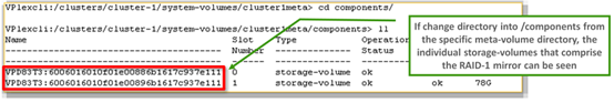
7.1.2 meta data volumes
meta data volumes 里包含 VPLEX cluster 的系统配置信息,主要为:
l virtual-to-physical mapping information
l data about the devices and virtual volumes
l system configuration settings
Meta data volume 建议为 Raid1 或者 Raid5 保护的卷,其对 I/O 性能的要求不高。
每个 VPLEX Metro cluster 安装需要 4 个 78GB 的 volume ,分别用于 meta-volume, mirrored copy of meta-volume, backups of meta-volume and mirrored-meta-volume.
| Cluster | Meta Volume | Storage | RAID Group | LUN ID | RAID | Size | 备注 |
| VPLEX_0001 | Mirror 1 | 800 | RAID5 | 78GB | |||
| Backup 1 | 801 | RAID5 | 78GB | 与HP 3PAR的系统共享磁盘 | |||
| Mirror 2 | 800 | RAID5 | 78GB | ||||
| Backup 2 | 801 | RAID5 | 78GB | 与HP 3PAR的系统共享磁盘 | |||
| VPLEX_0002 | Mirror 1 | 900 | RAID5 | 78GB | |||
| Backup 1 | 901 | RAID5 | 78GB | 与DS4800系统共享磁盘 | |||
| Mirror 2 | 900 | RAID5 | 78GB | ||||
| Backup 2 | 901 | RAID5 | 78GB | 与DS4800的系统共享磁盘 |
7.1.3 logging volumes
Loggging volume 用于在 inter-link 断开时,记录 Site 之间的数据差异索引。建议 logging volumes 为 10GB 的 volume , 10GB 的 logging volume 通常可以支持约 320TB 的分布式卷。
| Cluster | Log Volume | Storage | RAID Group | LUN ID | RAID | Size | 备注 |
| VPLEX_0001 | Mirror 1 | 802 | RAID5 | 10GB | 与HP 3PAR的系统共享磁盘 | ||
| Mirror 2 | 802 | RAID5 | 10GB | 与HP 3PAR的系统共享磁盘 | |||
| VPLEX_0002 | Mirror 1 | 902 | RAID5 | 10GB | 与DS4800系统共享磁盘 | ||
| Mirror 2 | 902 | RAID5 | 10GB | 与DS4800系统共享磁盘 |

1.1 Switch zoning
按照规划完成 VPLEX backend zoning
1.2 Backend storage provisionq
Register VPLEX BE port on HP3PAR
Assign volume to VPLEX
1.3 VPLEX initial setup
1.3.1 Configip address and hostname of VPLEX
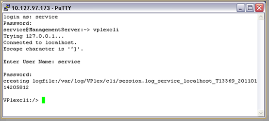
1.3.1.1 Connect to management server
connectEthernet cable to the service port of mgmt server. Config your NIC use DHCP, ip address will be assigned in the range 128.221.252.<23-30>
Default user/password :service/Mi@Dim7T
Service port IP: 128.221.252.2
SSH client: SecureCRT or PUTTY


1.1.1 use EZ-setup to initialize the VPLEX2
1.1.1.1 Connect to VPLEX2
Use SSH to connect to management IP of cluster 2,
1.1.1.2 Sychronize the time on the clusters
1.1.1.3 Start EZ-setup on cluster2

1.1.1.1 Configure the Meta-data volume and backup of VPLEX2
Use the same method to configure the VPLEX2 meta-data volumes and backups
1.1.1.1 Complete configuration of cluster1

1.1.1.2 Complete configuration of cluster2

1.1.1 oin the clusters
From Vplexcli on cluster2 console, run the following command,


1.1 Check the cluster health

1.1 VPLEX backend storage connectivity verify
1.1 Claim the data volume
l check if VPLEX can see the backend arrays
l
| VPlexcli:/>ls -al /clusters/cluster-1/storage-elements/storage-arrays/ /clusters/cluster-1/storage-elements/storage-arrays: Name Connectivity Auto Ports Logical --------------------------- Status Switch ------------------- Unit --------------------------- ------------ ------ ------------------- Count --------------------------- ------------ ------ ------------------- ------- EMC-CLARiiON-FNM00094200051 ok true 0x50060160446019f5, 252 0x50060166446019f5, 0x50060168446419f5, 0x5006016f446019f5 |
l check backend volumes
| VPlexcli:/>ls –al /clusters/cluster-1/storage-elements/storage-volumes/ /clusters/cluster-1/storage-elements/storage-volumes/: Name VPD83 ID Capacity Use Vendor IO Status Type Thin Rebuild ---- -------- -------- --- ------ ---------- ----- ----------- VPD83T3:6006016031111000d4991c2f7d50e011 VPD83T3:6006016031111000d4991c2f7d50e011 5G unclaimed DGC alive traditional false |
l if can not see the volumes, use command to re-discover
| VPlexcli:/>cd /clusters/cluster-1/storage-elements/storage-arrays/EMC-CLARiiON-FNM00094200051 VPlexcli:/clusters/cluster-1/storage-elements/storage-arrays/EMC-CLARiiON-FNM00094200051/>array re-discover WARNING: This command cannot detect LUN-swapping conditions on the array(s) being re-discovered. LUN swapping is the swapping of LUNs on the back-end. This command cannot detect LUN swapping conditions when the number of LUNs remains the same, but the underlying actual logical units change. I/O will not be disrupted on the LUNS that do not change. Continue? (Yes/No) y |
l claim the data volumes
Claim by use parameter “--appc” to ensure application consistency, because we have data on one leg of the mirror.
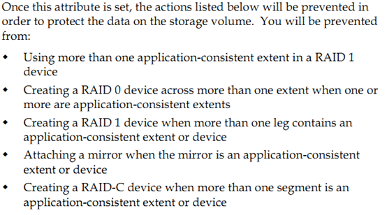
| VPlexcli:/>storage-volume claim -d VPD83T3:6006016031111000d4991c2f7d50e011 -n lun_1 --appc This can be confirmed by checking the Type of the storage-volume which should display as data-protected. VPlexcli:/>ls –al /clusters/cluster-1/storage-elements/storage-volumes/ Name VPD83 ID Capacity Use Vendor IO Status Type Thin Rebuild ---- -------- -------- --- ------ --------- ----- ----------- lun_1 VPD83T3:6006016031111000d4991c2f7d50e011 5G used DGC alive data-protected false |
1. 设备的使用
1**
1.1 Vplex 的使用
使用英文版的 Web browser: Firefox v3.5.5 or v3.5.7, or Internet Explorer 7 (安装 Adobe Flash Player 10.0.0 or higher 插件)输入 https:// 设备管理 IP
**
2. 系统测试
2**
2.1 Vplex 高可用测试
a) 测试场景一:主机的一个光纤卡故障
| 测试步骤 | 预期结果 |
| · 用powermtdisplay dev=all检查设备和路径状况 · 打开iometer对lun进行写操作 · 关闭一台服务器的HBA卡 · 再次用powermtdisplay dev=all检查设备和路径状况 | powermt的输出中hdiskpower#的两个通道上都有IO流量,且IO总流量比较接近。 |
b) 测试场景二: VPLEX 的一个 Director 故障
| 测试步骤 | 预期结果 |
| · 用powermtdisplay dev=all检查设备和路径状况 · 打开iometer对lun进行写操作 · 在putty连接vplex后director-1-1-b:/opt/zephyr/bin # /sbin/shutdown -h now · 再次用powermtdisplay dev=all检查设备和路径状况 | powermt的输出中hdiskpower#的两个通道上都有IO流量,且IO总流量比较接近。 |
c) 测试场景三: VPLEX 后端存储的一个控制器故障
| 测试步骤 | 预期结果 |
| · 用powermtdisplay dev=all检查设备和路径状况 · 打开iometer对lun进行写操作 · 拔掉director a上与交换机连接的光纤 · 再次用powermtdisplay dev=all检查设备和路径状况 | powermt的输出中hdiskpower#的四个通道上都有IO流量,且IO总流量比较接近。 |
d) 测试场景四: VPLEX 后端一台存储故障
| 测试步骤 | 预期结果 |
| · 用powermtdisplay dev=all检查设备和路径状况 · 打开iometer对lun进行写操作 · 关闭其中一台存储 · 再次用powermtdisplay dev=all检查设备和路径状况 | powermt的输出中hdiskpower#的四个通道上都有IO流量,且IO总流量比较接近。 |
2.2 数据库高可用测试

a) 测试场景一:主机的一个光纤卡故障
| 测试步骤 | 预期结果 |
| · 用powermtdisplay dev=all检查设备和路径状况 · 在数据库中插入数据 · 关闭一台服务器的HBA卡 · 再次用powermtdisplay dev=all检查设备和路径状况 | Oracle正常运行 |
b) 测试场景二: VPLEX 的一个 Director 故障
| 测试步骤 | 预期结果 |
| · 用powermtdisplay dev=all检查设备和路径状况 · 在数据库中插入数据 · 在putty连接vplex后director-1-1-b:/opt/zephyr/bin # /sbin/shutdown -h now · 再次用powermtdisplay dev=all检查设备和路径状况 | Oracle正常运行 |
c) 测试场景三: VPLEX 后端存储的一个控制器故障
| 测试步骤 | 预期结果 |
| · 用powermtdisplay dev=all检查设备和路径状况 · 在数据库中插入数据 · 拔掉director a上与交换机连接的光纤 · 再次用powermtdisplay dev=all检查设备和路径状况 | Oracle正常运行 |
d) 测试场景四: VPLEX 后端一台存储故障
| 测试步骤 | 预期结果 |
| · 用powermtdisplay dev=all检查设备和路径状况 · 在数据库中插入数据 · 关闭其中一台存储 · 再次用powermtdisplay dev=all检查设备和路径状况 | Oracle正常运行 |
e) 测试场景四: VPLEX 后端一台存储故障
| 测试步骤 | 预期结果 |
| · 用powermtdisplay dev=all检查设备和路径状况 · 在数据库中插入数据 · 断开WAN COM链路 · 再次用powermtdisplay dev=all检查设备和路径状况 | Oracle正常运行,节点二offline。 |
如果觉得我的文章对您有用,请点赞。您的支持将鼓励我继续创作!
赞1作者其他文章
评论 6 · 赞 9
评论 0 · 赞 4
评论 6 · 赞 6
评论 2 · 赞 4
评论 0 · 赞 2
添加新评论0 条评论